Spacing-to-height ratio is useful only when it is treated as a maximum-spacing gate, not as a universal rule of thumb that replaces photometric design. The buyer should calculate the fixture spacing envelope first, then ask whether the real room, task plane, obstruction pattern, and safety requirement still support that layout.
DLC spacing criteria glossary defines spacing criterion as an estimated maximum ratio of luminaire spacing to mounting height above the work plane for acceptable uniformity in a regular array. That definition is the key: the ratio is tied to a luminaire, a mounting height, a work plane, and a regular layout. It is not a universal number that can be copied from one warehouse, parking deck, or production hall to another.
Key Takeaways
- Spacing-to-height ratio, often written as S/MH, compares center-to-center fixture spacing with mounting height above the work plane, not simply ceiling height.
- The maximum spacing is usually estimated from the product spacing criterion multiplied by mounting height, then checked with photometric software.
- Dark spots appear when actual spacing, beam distribution, reflectance, or obstructions exceed what the luminaire can cover uniformly.
- A higher lumen package does not automatically fix a bad layout because it can raise contrast, glare, and hot spots.
- Fanxstar buyers should send ceiling height, mounting height, grid spacing, task plane, beam need, and obstruction notes before approving a sample.
What the Spacing-to-Height Ratio Actually Measures
Use mounting height above the work plane, not a loose ceiling number
According to DLC spacing criteria glossary, spacing criterion is an estimated maximum ratio of luminaire spacing to mounting height above the work plane. That wording prevents a common S/MH error. If a fixture is suspended below the ceiling, the useful mounting height is lower than the ceiling height. If the task plane is a workbench, shelf level, floor, or road surface, the reference plane changes the calculation.
A simple example shows the difference. A warehouse may have a 10 m roof, but suspended luminaires sit at 8.5 m and the work plane is 0.8 m above the floor. The useful mounting height above the work plane is 7.7 m, not 10 m. If the buyer uses the roof height, the fixture grid may be too wide and the installed floor can show alternating bright and dark bands.
The formula is simple; the assumptions are not
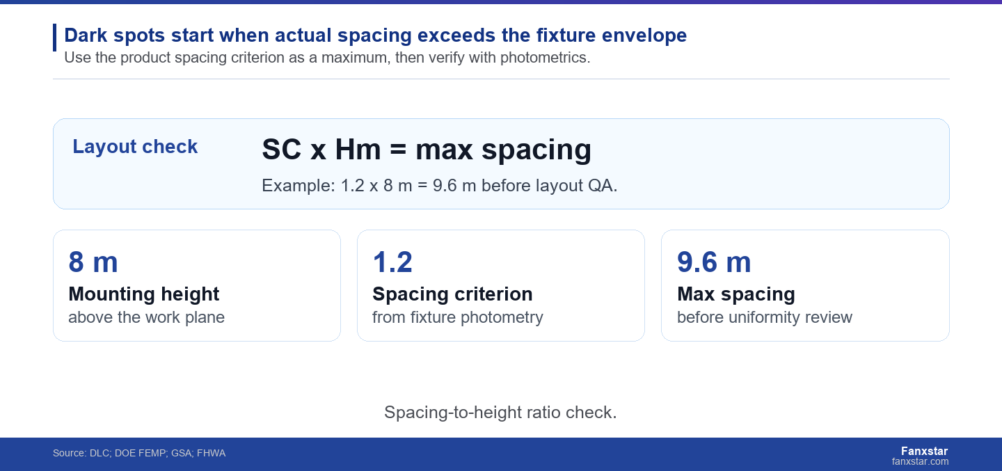
The first-pass formula is straightforward: maximum center spacing equals spacing criterion multiplied by mounting height above the work plane. If a fixture has a spacing criterion of 1.2 and the useful mounting height is 8 m, the first-pass maximum spacing is 9.6 m. A 9 m grid may be reasonable for review; a 12 m grid should trigger a recalculation or a different optic.
The formula does not approve the project by itself. It assumes a regular luminaire array and a work plane where direct illuminance is the main concern. Open areas rarely stay that clean. Racking, suspended equipment, mezzanines, vehicle lanes, camera views, emergency routes, dark surfaces, and wall setbacks can all change the real uniformity. The ratio is the first gate, not the final design.
Why Dark Spots Appear Even When Average Lux Looks Fine
Average illuminance can hide contrast failure
According to FEMP parking lot lighting guidance, lighting uniformity on pavement is important for safe vehicle and pedestrian interaction, and uniform lighting helps both camera viewing and physical viewing. The same principle applies indoors. A lighting layout can meet an average lux target while still producing dark zones where workers, pallets, vehicles, or hazards are harder to see.
Dark spots usually come from one of four mechanisms: overspacing, narrow distribution, blocked light paths, or low reflectance. Higher wattage can increase average lux, but it may also create brighter pools beneath fixtures and leave contrast between rows. That is why spacing-to-height ratio should be paired with uniformity review, not used as a shortcut to justify fewer fixtures.
Beam angle and optical distribution decide how far spacing can stretch
| Field condition | What changes in the ratio | What to request |
|---|---|---|
| High mounting height | More spacing may be possible, but beam angle and glare still matter. | Photometric layout at the actual mounting height. |
| Low suspended fixtures | Effective mounting height drops, so spacing must usually tighten. | Updated S/MH calculation above the work plane. |
| Dark floors or walls | Less reflected light can make dark zones more visible. | Reflectance assumptions in the lighting model. |
| Aisles, racking, ducts, or machines | Obstructions break the regular array assumption. | Zone-based layout rather than one open-area average. |
| Camera or pedestrian safety need | Uniformity and vertical visibility may matter more than average lux. | Uniformity and task-plane checks for the actual route. |
A wide distribution can tolerate a wider grid in some open areas, while a narrow high-bay optic may need tighter spacing even at the same mounting height. Linear fixtures add another layer because the spacing in the fixture direction and across rows may differ. A buyer comparing two LED products should therefore compare photometric files and layout results, not only lumens per fixture.
According to FEMP purchasing guidance for LED luminaires, federal purchasing guidance includes categories such as high-bay, low-bay, and linear ambient luminaires. That matters because product category affects the distribution pattern. A parking deck vapor-tight fixture, a warehouse high bay, and a linear aisle fixture may all be LED upgrades, but their spacing envelopes are not interchangeable.
How to Use the Ratio in an RFQ or Retrofit Plan
Ask for the fixture envelope before asking for the final count
A strong RFQ asks the supplier to state the fixture spacing criterion, beam distribution, intended mounting height, task plane, target illuminance, and expected uniformity. It also asks whether the proposed grid is inside the spacing envelope or requires a photometric exception. This prevents the supplier from quoting fewer fixtures only to win the first comparison.
According to DLC technical requirements for solid-state lighting, commercial LED product evidence is organized around product category and performance reporting. For spacing, the equivalent discipline is to attach the photometric file, layout drawing, mounting height, surface reflectance, and uniformity output to the quote. Without those items, the buyer cannot tell whether a cheap fixture count is efficient or simply under-designed.
According to ENERGY STAR upgrade lighting guidance, LED lighting upgrades can serve commercial applications such as parking garages and task lighting. This means a single spacing shortcut is especially risky in mixed-use facilities, where task areas, vehicle routes, and storage zones need different layouts even inside one upgrade package.
Use wall rows, aisle rows, and obstacle zones as separate checks
Open-area layouts often fail at the edges. A wall row is not the same as a center row because it may need half-spacing, wall-wash control, or task-specific coverage. A racked aisle is not the same as an open production zone because vertical surfaces and shadows matter. A parking entry is not the same as an interior deck because eye adaptation and pedestrian movement can change the visual task.
According to FHWA crosswalk lighting research, mounting height, vertical illuminance, and geometry all affect roadway and pedestrian lighting calculations. The lesson for commercial LED buyers is broader: where people need to see objects, faces, vehicles, labels, or hazards, horizontal average lux is not enough. The layout should match the real visual task and viewpoint.
Illustrative Spacing Check for a Warehouse or Parking Area
A 25 percent spacing overrun is a design warning, not a rounding error
Assume a fixture spacing criterion of 1.2 and a useful mounting height of 8 m. The first-pass maximum spacing is 9.6 m. If the quote proposes a 12 m grid, the actual spacing-to-height ratio is 1.5. That is 25 percent higher than the product envelope. The layout may still be possible with a different optic or higher mounting height, but it should not pass without photometric proof.
According to DLC quick facts, qualified lighting product lists are used widely by utility and energy efficiency programs. The decision rule for layout evidence should be just as strict: a fixture should not be treated as suitable for a wide grid unless the selected model, optics, and mounting condition can be tied to a verifiable photometric file.
This calculation is illustrative, not a universal design rule. The exact acceptable grid depends on the luminaire photometry, room dimensions, task plane, reflectance, target illuminance, uniformity requirement, glare limit, and safety context. The value of the calculation is that it forces the buyer to ask why a wider grid is acceptable before the fixture count becomes the budget.
When wider spacing can be reasonable
Wider spacing can work when the luminaire has a suitable wide distribution, mounting height is high enough, surfaces are reflective, the task is low-risk, and the photometric model confirms uniformity. It can also work when the layout is designed around lower target light levels and the application accepts wider contrast. The mistake is not wide spacing itself; the mistake is wide spacing without proof.
Tighter spacing can also be wrong. Too many fixtures or too narrow a grid can create overlighting, glare, installation cost, control complexity, and maintenance burden. A good LED layout balances uniformity, glare, energy, control zoning, access, and cost. Spacing-to-height ratio helps start that balance, but the final decision should be a layout package rather than a single formula result.
According to GSA LED and controls guidance, linear lighting choices should consider life-cycle cost and controls behavior. This means layout review should include the control zones too. A design that looks uniform at 100 percent output can still feel patchy if sensors dim adjacent zones unevenly or if the emergency route uses a different control schedule.
How Fanxstar Buyers Should Specify Spacing Evidence
Send geometry before asking for a fixture recommendation
Fanxstar can give a stronger recommendation when the RFQ includes ceiling height, mounting height, work plane, fixture row spacing, room dimensions, wall reflectance, obstruction map, target lux, uniformity target, beam preference, and control zones. That applies to parking garage LED lighting, tunnel LED lighting, food processing plant lighting, and warehouse and logistics LED lighting.
If the buyer only sends area size and requested wattage, the response may default to a generic fixture count. If the buyer sends geometry and task requirements, the supplier can decide whether a weatherproof linear, vapor-tight, high-bay, batten, or sensor-ready fixture is more appropriate. That difference is where ODM support becomes useful.
Freeze the spacing logic before sample or bulk order
For a custom or platform-adapted project, use Fanxstar custom LED lighting ODM service to discuss optic, diffuser, CCT, sensor, emergency function, and mounting changes before the sample is locked. A change in diffuser, lens, LED board, sensor position, or mounting accessory can change the light distribution. If the distribution changes, the spacing logic should be checked again.
The buyer’s release file should include a drawing, fixture model, mounting height, spacing grid, photometric file, target illuminance, uniformity output, and any site assumptions. If the installed site differs from the model, the project team should know which assumption changed. That is how a ratio becomes a controlled engineering decision rather than a guess.
FAQ
What is spacing-to-height ratio in lighting?
Spacing-to-height ratio, or S/MH, compares the distance between luminaire centers with the mounting height above the work plane. It helps estimate how far fixtures can be spaced while maintaining acceptable uniformity, but the final layout still needs photometric verification for the real room and task.
Can I use one spacing ratio for every LED fixture?
One spacing ratio should not be used for every LED fixture because the usable ratio depends on photometry, beam distribution, mounting height, task plane, surface reflectance, and application. Two LED fixtures with similar wattage can need different spacing because their optical distributions are different.
Why do dark spots appear after an LED retrofit?
Dark spots usually appear after an LED retrofit when fixtures are over-spaced, mounted lower than assumed, blocked by racking or ducts, placed with the wrong beam distribution, or selected by lumen output without a uniformity check. Average lux alone can hide these contrast problems.
What should I send Fanxstar for spacing review?
For spacing review, send room dimensions, ceiling and mounting height, work plane, current or proposed grid, target lux, uniformity target, obstacle map, application type, fixture category, control zones, and any existing photometric layout. That lets Fanxstar review fixture fit instead of guessing from area size.