An LED luminaire that performs flawlessly in photometric testing can still fail CE certification at the EMC test lab — and understanding why is not always intuitive. The switch-mode power supply inside every LED driver is an efficient but inherently noisy source of electromagnetic interference: it switches at tens to hundreds of kilohertz, generating harmonics that propagate both through the mains wiring (conducted emissions) and through the air (radiated emissions). Getting a luminaire to pass EN 55015 / CISPR 15 consistently requires engineering discipline from schematic through final housing — and a clear understanding of where the noise originates and how it escapes.
Key Takeaways
- Conducted emissions (150 kHz – 30 MHz) and radiated emissions (9 kHz – 300 MHz for lighting) are tested separately under CISPR 15 / EN 55015, and each has distinct root causes and fixes.
- The LED driver’s switching frequency and its harmonics are the dominant noise sources — and the LED string itself, due to its length and layout, can act as an effective antenna above 30 MHz.
- Most first-time EMC failures in LED luminaires trace to three root causes: inadequate mains-side filtering, poorly grounded enclosures, or LED PCB layouts with large current loops.
Why EMC Matters for LED Luminaires Specifically
LED luminaires contain a switch-mode power supply (SMPS) in the driver, which is a fundamentally different electromagnetic situation from the resistive or magnetic loads in older lighting technologies. The SMPS switches its output transistors on and off at high frequencies — typically between 20 kHz and several hundred kHz for common LED driver topologies — and each switching transition generates voltage and current spikes with edge rates measured in nanoseconds. These fast edges contain harmonic content that extends from the switching fundamental well into the MHz range.
Unlike a desktop computer where all electronics are enclosed in a grounded metal chassis, an LED luminaire has a problem unique to its application: the LED string itself — often mounted on a PCB spanning 600 mm, 1200 mm, or more — must be optically exposed to emit light, which means it cannot be shielded. A long LED string carrying pulsed current is, electrically, a large current loop. A large current loop at high frequencies is an efficient antenna. This is why, as Analog Devices has noted, radiated emissions from LED drivers can be particularly high compared to other electronics categories of similar power.
The Governing Standard: CISPR 15 / EN 55015
For general-purpose LED luminaires, the primary EMC emission standard in Europe is EN 55015 (the European adoption of international CISPR 15). The standard defines conducted disturbance limits at mains terminals (9 kHz – 30 MHz) and radiated emission limits measured with loop antennas (9 kHz – 30 MHz for magnetic field, and up to 300 MHz for electric field in the case of LED products). In Australia and New Zealand, the equivalent is AS/NZS CISPR 15, and ACMA accepts compliance to EN 55015 as an alternative. Additionally, EN 61000-3-2 governs harmonic current limits (lighting is treated as Class C equipment, with a 25 W threshold, not the 75 W threshold used for other products). The EU EMC Directive 2014/30/EU and, for luminaires with integrated wireless control (Zigbee, Bluetooth, DALI 2.0 wireless), the Radio Equipment Directive 2014/53/EU (RED) also apply.
Conducted Emissions: Root Causes and Fixes
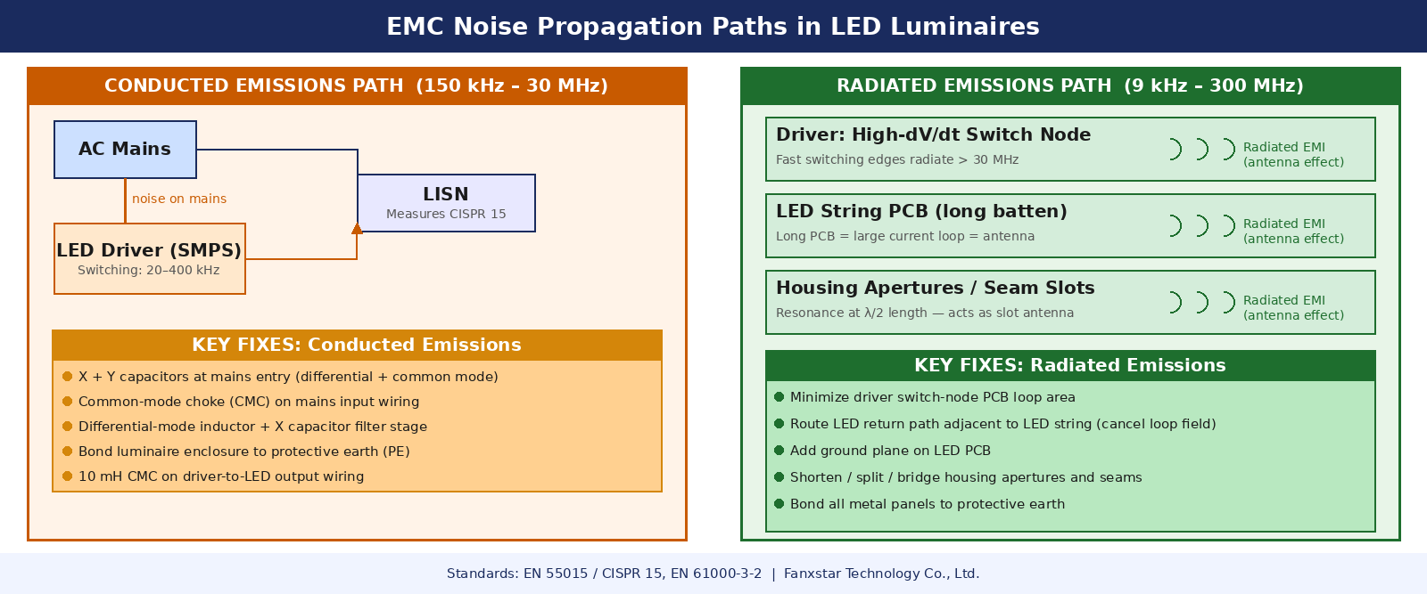
Conducted emissions are electromagnetic noise currents that travel out of the luminaire back onto the AC mains supply line. They are measured using a Line Impedance Stabilization Network (LISN), which provides a standardized impedance at the measurement port. The LISN outputs a voltage signal proportional to the conducted noise on each mains conductor, which is then measured by an EMI receiver across the 9 kHz – 30 MHz range. The most common failure mode in LED luminaire conducted emissions testing is a series of peaks at the driver’s switching frequency and its harmonics, typically appearing as regularly spaced spikes on the scan plot.
Root Cause 1: Absence of Mains-Side EMI Filter
The single most common reason LED luminaires fail conducted emissions tests — especially lower-cost fixtures — is the omission of a proper input EMI filter from the driver design. Research from the field has documented fixtures exceeding CISPR 15 limits by 30 dB or more across the HF communications band (1 – 30 MHz), with adding ferrite chokes only achieving a 20–30 dB improvement that still leaves the fixture non-compliant. An adequate mains filter for an LED driver must include both differential-mode filtering (an X capacitor and inductor addressing noise between the two supply conductors) and common-mode filtering (a common-mode choke and Y capacitors addressing noise between the supply conductors and earth). The filter component values must be designed for the driver’s specific switching frequency and its harmonic profile — a single generic filter value will not address all failure modes.
Root Cause 2: Common-Mode Noise Path Through Driver-to-LED Wiring
Even with an adequate mains filter, conducted emissions can be driven by parasitic capacitance between the primary switching circuits and the secondary (LED) side of the driver, particularly in flyback and buck-boost topologies where primary-side high-dV/dt nodes are physically close to the secondary winding or output traces. This creates a capacitively coupled common-mode noise path that bypasses the input filter entirely. The preferred solution is to add a common-mode choke on the output wiring between the driver and the LED PCB, combined with Y capacitors from the output commons to the luminaire earth ground. A 10 mH common-mode choke can provide approximately 62.8 kΩ of impedance at 1 MHz — far greater than what a single ferrite bead offers in that frequency range.
Root Cause 3: Floating Metal Enclosure
A metallic luminaire housing that is not properly bonded to earth ground can worsen conducted emissions significantly. When the enclosure is capacitively coupled to noisy PCB circuitry but has no intentional path to ground, it becomes a noise antenna, coupling energy back onto the mains through parasitic impedances. Ensuring that the luminaire’s metal housing is connected to the protective earth conductor with a low-impedance bond — verified with an earth continuity test, not just a visual inspection — is a prerequisite for reliable conducted emissions performance.
Radiated Emissions: Root Causes and Fixes
Radiated emissions are harder to troubleshoot systematically than conducted emissions because they depend on the physical geometry of the complete luminaire — the PCB layout, the LED string length and routing, the housing apertures, and the cable harness configuration. Unlike conducted noise, which can be reduced predictably by adding filter components, radiated emission reduction often requires iterative pre-compliance testing and physical design changes.
Root Cause 1: Large Current Loop Area on the LED PCB
The switching current from the LED driver flows through the LED string and returns via a separate conductor. The area enclosed between the forward and return current paths is the effective loop area, and loop area drives radiated emission efficiency at a given frequency. Long linear LED PCBs (600 mm, 1200 mm) with separated forward and return traces are efficient radiators above 30 MHz. The engineering solution is to route the LED return path as physically close to the LED forward path as possible — using an adjacent trace on a two-layer PCB or, better, a ground plane layer that mirrors the LED string on the opposite side. Every millimeter of loop area reduction at these dimensions meaningfully reduces radiated emission amplitude.
Root Cause 2: High-dV/dt Switching Node Layout on the Driver PCB
Within the driver PCB itself, the critical high-frequency emitting nodes are the transistor switch node (the junction between the switching FET, the inductor, and the rectifier diode) and the output capacitor wiring. The physical area of the circuit loop formed by the switch node, the inductor, the output diode, and the output capacitor must be minimized in the PCB layout. Components in these paths should be placed as compactly as possible, with trace lengths measured in millimeters, not centimeters. Analog Devices EMC design guidance notes that these high-dV/dt and high-dI/dt paths must be designed as small and compact as possible to reduce radiated emissions — this is not aesthetic preference, it is functional EMC design.
Root Cause 3: Enclosure Apertures and Seam Resonances
Metal enclosures attenuate radiated emissions well below their cutoff frequencies, but openings — ventilation slots, lens mounting gaps, gland entries — allow internal fields to escape. Slots are particularly problematic: a slot acts as a slot antenna, and its resonant frequency is determined by its length (resonance at approximately λ/2). For a 150 mm slot, the first resonance occurs around 1 GHz. In practice, luminaire manufacturers must minimize slot lengths (multiple short slots parallel to each other are better than one long slot), ensure all metallic cover panels are bonded together with multiple contact points, and use conductive gaskets or EMI-absorbing foam at critical seams if aperture management alone is insufficient.
EMC Compliance Checklist for LED Luminaire Qualification
| Stage | Check Item | Addresses |
|---|---|---|
| Driver Selection | Select driver with integrated EMI filter or verified CISPR 15 compliance at rated output | Conducted |
| Driver PCB | Minimize switch-node loop area; place X/Y caps and CMC close to mains entry | Conducted + Radiated |
| LED PCB | Route return path adjacent to LED string; add CMC on driver-to-LED wiring if needed | Radiated |
| Housing | Bond all metal panels to PE; minimize slot lengths; verify earth continuity | Radiated + Conducted |
| Pre-Compliance Testing | Pre-screen with EMI receiver + LISN before formal lab submission; test in worst-case configuration | Both |
| Documentation | Retain third-party test report specifying EN 55015 and EN 61000-3-2 for CE Declaration of Conformity | Compliance record |
What OEM Buyers Should Demand From a Manufacturer
For lighting distributors and OEM buyers sourcing weatherproof or industrial LED luminaires for EU and Australian markets, EMC documentation requirements should be treated as non-negotiable qualification criteria. A complete EMC compliance package for a CISPR 15 / EN 55015 product should include a third-party test report from an accredited laboratory specifying the emission plots for both conducted disturbance (mains terminals, 9 kHz – 30 MHz) and radiated disturbance (magnetic field, 9 kHz – 30 MHz), with pass/fail determination against the applicable limits. The test report should reference the specific luminaire model and configuration tested — not a generic driver module tested in isolation.
When evaluating manufacturers who offer OEM/ODM customization services, ask specifically whether EMC testing is conducted at the luminaire level (final housing, cable configuration, and all components assembled) or at the component level (driver only). A driver that passes CISPR 15 in an open-frame test fixture may not pass when integrated into a 1.2 m tri-proof fixture with specific wiring arrangements. Manufacturers who test at the luminaire level — and who can provide production-batch consistency guarantees — offer substantially lower compliance risk for downstream certification obligations.
Frequently Asked Questions
Does DALI 2.0 integration change a luminaire’s EMC test requirements?
Yes — and this is often overlooked. A luminaire with DALI 2.0 control still falls under EN 55015 / CISPR 15 for its light-source emissions, but the DALI interface is a digital communication signal that may generate additional emissions. If the DALI interface includes wired-only communication, the EMC Directive (2014/30/EU) remains the applicable framework, with additional immunity testing per EN 61547. If the luminaire includes any radio interface (Zigbee, Bluetooth, or 2.4 GHz RF), the Radio Equipment Directive (RED, 2014/53/EU) takes over as the primary regulatory framework, requiring spectrum management assessment in addition to emissions and immunity testing.
Why does my luminaire pass pre-compliance testing but fail at the formal test lab?
The most frequent reasons are configuration differences between pre-compliance and formal test conditions: cable lengths and routing that differ from the as-tested configuration, firmware operating modes that do not represent worst-case emission state, and the absence of a proper ground plane during pre-compliance (bench testing without a conductive ground plane produces significantly different antenna effects than a properly set-up OATS or semi-anechoic chamber). Full configuration control — standardizing the cable harness, the operating mode, the mounting configuration — between pre-compliance and formal lab submission is the single most impactful way to reduce test day surprises.
Is EN 55015 the same standard required for the Australian SAA mark?
Australia requires compliance with AS/NZS CISPR 15 for lighting equipment EMC. However, the Australian Communications and Media Authority (ACMA) accepts compliance demonstrated to the international equivalent CISPR 15 and the European EN 55015 as alternatives to AS/NZS CISPR 15. A test report from an accredited laboratory demonstrating conformance to EN 55015 is therefore acceptable for Australian market supply, provided the test scope (frequency range, measurement configuration) matches the AS/NZS CISPR 15 requirements.
Can a single luminaire test report cover multiple wattage variants in an OEM product line?
Typically, no — each significant variant (different driver, different PCB layout, different housing length) should be treated as a separate product for EMC testing purposes. However, if a product family uses an identical driver and PCB design with only physical mounting changes (e.g., different bracket), a manufacturer can sometimes make a technical justification for family testing. Any such justification must be documented in the technical file and validated by the accredited test laboratory. When in doubt, testing the highest-power variant (which typically produces the highest emission levels) as the worst case is a defensible approach with appropriate engineering justification.
Choosing an LED manufacturer who understands EMC requirements from the driver selection stage to the final housing design — and who backs that knowledge with third-party test documentation — directly reduces your certification timeline and product liability exposure. Fanxstar’s engineering team works with OEM clients and distributors to deliver weatherproof and industrial LED solutions with full CE technical file support, including EN 55015 and EN 61000-3-2 test reports for EU market distribution. Explore Fanxstar’s OEM/ODM capabilities or contact us to discuss your compliance requirements.