Video production professionals who have switched to LED ceiling lighting often encounter the same unpleasant surprise: footage shot under fixtures that look perfectly stable to the naked eye shows rhythmic banding, strobing, or exposure variation when reviewed at full resolution. The problem is temporal light modulation — and it is directly caused by how the LED driver manages current. For a studio operator, podcast host, corporate videographer, or content creator outfitting a dedicated production space with overhead battens, selecting the right LED batten fixture requires understanding five specific technical criteria that standard luminaire datasheets rarely highlight. This guide covers what those criteria are, what numbers to demand, and how to verify them before purchase.
Key Takeaways
- Camera-visible LED flicker is caused by PWM dimming frequencies below 25 kHz interacting with the camera’s shutter speed — and can occur even at frequencies that are invisible to the naked eye.
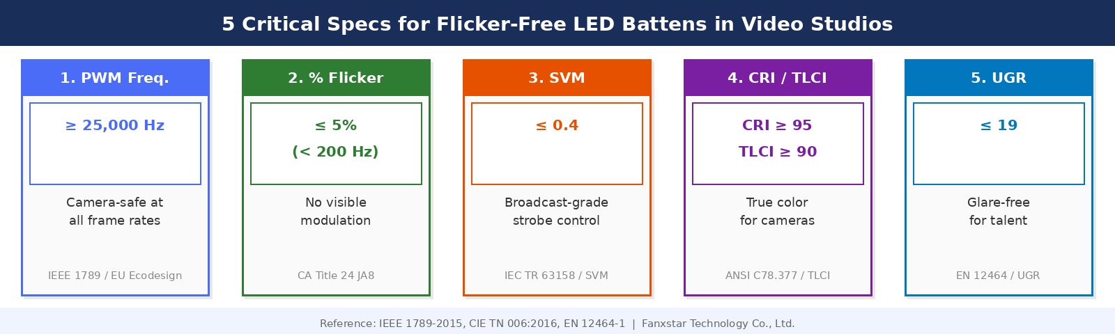
- For video studio applications, specify LED battens with PWM frequency ≥ 25 kHz, Percent Flicker ≤ 5%, Stroboscopic Visibility Measure (SVM) ≤ 0.4, CRI ≥ 90 (ideally ≥ 95), and UGR ≤ 19.
- The driver — not the LED chip — determines a fixture’s flicker performance. Two battens with identical LED specs but different drivers can produce completely different results on camera.
Why LED Batten Fixtures Flicker on Camera
Most white LED fixtures designed for general commercial use employ Pulse Width Modulation (PWM) for dimming — a technique that rapidly switches the LED between fully on and fully off at a fixed frequency to achieve a dimmed appearance. The perceived brightness corresponds to the proportion of time spent in the “on” state (the duty cycle). At PWM frequencies below approximately 100 Hz, flicker is directly visible to the human eye as a strobe effect. Between 100 Hz and 1.25 kHz, it becomes invisible to most observers but remains detectable by cameras, particularly at higher frame rates or when combined with certain shutter speeds. Above 1.25 kHz, sources that exhibit 100% modulation depth — such as PWM dimmers — become generally acceptable, but residual stroboscopic effects on moving subjects remain possible up to 3 kHz and potentially beyond.
The interaction between PWM frequency and camera shutter speed determines whether banding appears in footage. If the PWM cycle and the camera’s shutter cycle are not in perfect synchrony or a whole-number ratio, the camera captures different portions of the LED’s on/off cycle in different frames — producing frames that vary in brightness and creating the characteristic rolling bands or flickering exposure that ruins otherwise clean footage. For high-frame-rate video (120 fps, 240 fps, or higher for slow-motion applications), the problem is amplified because the shorter inter-frame period makes frequency mismatches more likely.
The Camera-Specific Risk: High Frame Rates and High Shutter Speeds
Standard broadcast video at 24 or 30 fps can be problematic with fixtures operating at 500 Hz PWM — a frequency sometimes marketed as “flicker-free” for human visual comfort. For high-speed video at 120 fps, 500 Hz PWM is still insufficient because the camera captures 120 images per second, and each of those images integrates over a very short shutter window. The recommendation from lighting engineers specializing in film and photography applications is to use LED drivers with PWM frequencies at or above 25,000 Hz (25 kHz). At this frequency, even high-frame-rate and high-shutter-speed applications are free of visible modulation effects, and the frequency is above the human audible range, eliminating the secondary problem of PWM-induced buzzing from driver components.
The Five Specifications That Determine Flicker Performance
1. PWM Dimming Frequency: ≥ 25 kHz
This is the single most important specification for camera environments. A driver operating at 25 kHz or above eliminates camera-visible flicker for virtually all practical frame rate and shutter speed combinations in professional video production. Fixtures marketed with PWM frequencies of 200–400 Hz are suitable for general commercial use and human visual comfort but will produce artifacts under high-speed camera capture. Always request the PWM frequency from the driver datasheet — not from the luminaire specification sheet, which often omits this detail.
2. Percent Flicker: ≤ 5%
Percent Flicker (PF) measures the amplitude of light output modulation as a ratio of the difference between maximum and minimum brightness to their sum, expressed as a percentage. A value of 0% indicates perfectly constant output; 100% means the source goes from fully on to fully off each cycle. For video environments, a PF of ≤ 5% at any frequency below 200 Hz is the target threshold — this aligns with the “flicker-free” designation used in California’s Title 24 building codes, which remains among the most stringent built-environment flicker standards globally. Note that PF alone is insufficient: a source with 100% modulation at 30 kHz is both camera-safe and human-safe, while a source with 10% modulation at 50 Hz is problematic. PF must always be evaluated alongside frequency.
3. Stroboscopic Visibility Measure (SVM): ≤ 0.4
SVM is the perceptual metric that quantifies the stroboscopic effect — the risk that moving objects appear to freeze, stutter, or produce ghost images under flickering light. It integrates modulation depth and frequency weighted against human visual system sensitivity across the 80 Hz to 2 kHz range, where stroboscopic effects are most biologically active. An SVM value of 1.0 represents the visibility threshold for an average observer; values above 1.0 indicate visible stroboscopic artifacts. For video studios and broadcast environments, the target is SVM ≤ 0.4, which provides significant margin against stroboscopic effects for both human occupants and moving subjects captured on camera. This threshold is also recommended for high-precision industrial tasks involving rotating machinery.
4. Color Rendering: CRI ≥ 90, R9 ≥ 50
Video cameras record and reproduce color faithfully only when the light source renders all spectral components of a subject accurately. A CRI of 90 or above ensures that skin tones, fabric colors, product hues, and environmental elements are reproduced with fidelity that matches the subject’s appearance under natural light. For studio environments where color accuracy is a production value — interview settings, product demonstrations, cosmetic applications — CRI 95 or above, with R9 (deep red rendering) ≥ 50, is the preferred specification. High-CRI phosphor LEDs typically require slightly more careful driver design to maintain consistent CCT under dimming, which is another reason driver quality matters in studio fixture selection. TLCI (Television Lighting Consistency Index) is an increasingly used companion metric specifically calibrated to broadcast camera response; a TLCI of 90+ is recommended for professional broadcast applications.
5. UGR ≤ 19
Unified Glare Rating (UGR) quantifies the discomfort glare experienced by occupants in a lit space. For a studio environment where talent, presenters, or subjects are positioned under overhead lighting and camera operators need to view monitors accurately, a UGR ≤ 19 minimizes squinting, pupil reflexes that affect camera focus, and discomfort for extended session durations. UGR is determined by the fixture’s luminance distribution, the room geometry, and the reflectance of surfaces — not by the fixture alone — but a fixture’s datasheet UGR value (usually stated for a defined room condition) provides a useful comparative baseline.
Constant Current Driver vs. PWM Dimming: The Architecture Difference
The alternative to PWM dimming is constant current reduction (CCR) dimming, sometimes called analog dimming, which reduces LED brightness by reducing the actual drive current rather than switching it on and off. CCR produces zero modulation at the drive frequency by definition — the output is genuinely constant at any dimming level. The tradeoff is that CCR causes a slight CCT shift as current decreases (LEDs shift warmer at lower currents), which can be a calibration issue in color-critical studio environments. Some high-quality LED drivers use a hybrid approach: analog dimming at higher light levels where CCT shift is perceptible, transitioning to high-frequency PWM (≥ 25 kHz) at lower levels where the CCT shift from CCR becomes more pronounced. For studio batten fixtures that will be dimmed and color-matched across a shoot, understanding which dimming topology the driver uses is essential.
| Parameter | Minimum for Video Studio | Professional Broadcast Target |
|---|---|---|
| PWM Frequency | ≥ 1 kHz | ≥ 25 kHz (or CCR) |
| Percent Flicker (< 200 Hz) | ≤ 30% | ≤ 5% |
| Stroboscopic Visibility (SVM) | ≤ 1.0 | ≤ 0.4 |
| CRI (Ra) | ≥ 90 | ≥ 95 (TLCI ≥ 90) |
| UGR | ≤ 22 | ≤ 19 |
| CCT | 4000K or 5600K (consistent with key lights) | 5600K daylight (matches professional film lights) or 3200K tungsten |
What to Ask an LED Manufacturer Before You Order
Flicker performance claims are difficult to evaluate from marketing datasheets alone. The reliable approach is to request specific documentation from the manufacturer before committing to an order. First, ask for the driver’s PWM frequency in Hz — not “high frequency” or “flicker-free” as a claim, but a numerical value. Second, ask for a flicker test report specifying Percent Flicker and Stroboscopic Visibility Measure (SVM) at 100% and at the minimum dimming level. Flicker performance often degrades at low dimming levels, and fixtures rated “flicker-free” at full output can develop problematic modulation at 20-30% brightness where they spend most of their operational time in dimmed studio environments. Third, ask for LM-79 photometric data including CRI, R9, and CCT. For broadcast applications, request TLCI measurement as well.
For OEM and custom-specification buyers developing studio-specific batten fixtures — media production companies, broadcast facility developers, or rental equipment manufacturers — the SKUs-IN-ONE approach is particularly relevant: a single fixture model with user-adjustable CCT (e.g., 3200K/4000K/5600K) and wattage selection eliminates the inventory complexity of maintaining separate warm, neutral, and cool batten stock for multi-purpose studio spaces. Prototype delivery timelines of 3–5 working days from a capable manufacturer enable real-world camera testing of the actual CCT and driver combination before production quantities are committed.
Frequently Asked Questions
Is a “flicker-free” marketing claim legally defined anywhere?
No regulatory framework globally mandates the specific use of the term “flicker-free” on a product label, and no single universal definition exists. California’s Title 24 and JA8 standards define “low flicker operation” as Percent Flicker ≤ 30% at frequencies below 200 Hz — a threshold that many professional users would not consider adequate for video work. IEEE Std 1789-2015 provides the most rigorous published framework for evaluating flicker safety, but it is a recommended practice, not a legally mandatory standard. When evaluating “flicker-free” claims, always request the underlying test data — specifically PWM frequency, Percent Flicker at the target dimming level, and SVM.
Can I test a fixture for camera-visible flicker before buying in quantity?
Yes. A practical preliminary test is to point a smartphone camera in slow-motion video mode (120 fps or higher) at the powered fixture while slowly sweeping the camera across the light source. Dark horizontal bands moving across the image indicate camera-visible PWM interaction. This is a qualitative screening tool only — it does not provide Percent Flicker or SVM measurements, and it will not reliably detect high-frequency PWM artifacts. For final qualification of studio fixtures, always request a third-party LM-79 or equivalent flicker measurement report from the manufacturer.
Does IP-rated weatherproof batten design affect flicker performance?
The IP rating (protection against dust and moisture) does not directly affect flicker performance — flicker is a function of driver electronics, not enclosure design. However, the constraints of an IP65 or IP66 enclosure can affect driver thermal management, which in turn affects driver operating stability. A driver that runs hotter due to restricted airflow in a sealed enclosure may exhibit increased output ripple at elevated temperatures. Manufacturers who design IP65+ battens specifically for studio or cleanroom environments (where both protection and color quality are required) should validate flicker performance at operating temperature, not only at room temperature.
Building a studio environment where every camera angle looks clean requires more than mounting lights on a ceiling — it requires specifying fixtures whose driver electronics are engineered for the demands of video capture. Fanxstar’s engineering team supports OEM and distributor clients in developing custom LED batten specifications that meet video studio, cleanroom, and commercial broadcast requirements. Explore our customization capabilities or contact us with your specification requirements.