A motion sensor master-slave configuration is not just extra wires between sensors; it is a control architecture that must define which device senses, which device switches the load, how the load is powered, and how the final LED fixtures are tested. In a long corridor, warehouse aisle, parking route, or back-of-house area, the buyer usually wants one lighting group to respond when motion is detected from more than one point. The project risk is assuming any two sensors can simply be tied together.
Remote Control Low Voltage Switching application guide says tying occupancy sensors together in a master-slave configuration allows any sensor in the group to turn on a single circuit. Lutron Maestro sensor specification also warns that only one occupancy sensor switch can be used per multi-location circuit for its listed configuration. The lesson is not contradiction; it is product-specific wiring architecture.
Key Takeaways
- A master-slave sensor scheme extends coverage, but the wiring method depends on the sensor family, voltage, load interface, and manufacturer limits.
- Do not assume two occupancy sensors can both switch the same LED load directly; some systems require a power pack, relay, companion switch, or low-voltage input module.
- Buyers should ask for interconnection diagrams covering power, signal, control wiring, load limits, and commissioning steps before approving sensor-ready luminaires.
- The fixture supplier, controls supplier, electrical designer, and installer must agree on the final wiring method before sample approval.
- Fanxstar sensor-ready lighting projects should test the final fixture, driver, sensor, and control logic as one system.
What Master-Slave Motion Sensor Wiring Means
The goal is shared coverage, not random parallel wiring
Master-slave is a practical phrase, but it can hide several architectures. In one system, a master device may switch the load while slave sensors provide sensing inputs. In another system, multiple low-voltage sensors may feed a relay or panel input. In a manufacturer-specific wall sensor system, only one sensing switch may be allowed, with companion devices used at other locations. The buyer should not translate the phrase into a wiring shortcut.
LAWA lighting controls guide specification states that corridor and hallway sensors can be wired in master-slave configuration to extend area of coverage. That is the application reason. The technical reason still depends on device model, Class 2 wiring, relay panel, load limit, voltage, and manufacturer instructions.
| Term | What it usually means | Buyer risk if unclear |
|---|---|---|
| Master sensor | The device or control point that owns the load command. | Two devices may fight for control or exceed wiring limits. |
| Slave sensor | A secondary sensing point extending coverage. | The slave may be wired as if it switches load directly. |
| Power pack or relay | The switching interface between low-voltage sensors and lighting load. | Load limits and control voltage may be misunderstood. |
| Companion switch | A manufacturer-approved multi-location device. | A second sensor may be incorrectly substituted. |
| Coverage zone | The area where occupancy must trigger the lighting group. | Dead zones or nuisance triggers appear after installation. |
The load-switching device must be identified
The most important question is who actually switches the LED load. If the answer is a wall sensor, the manufacturer may limit multi-location behavior. If the answer is a low-voltage input module or relay panel, the sensors may only provide signals. If the answer is a power pack, load rating and sensor current become the gate. Without that answer, the buyer cannot judge whether the configuration is safe or scalable.
Lutron Maestro occupancy sensor installation resources separates model-specific installation resources, and the specification sheet gives explicit multi-location restrictions. That is why the supplier should not answer master-slave wiring with a generic diagram. The diagram must match the selected model.
What Buyers Should Verify Before Installation
Ask for power, signal, and control wiring diagrams
University of Houston lighting control devices specification asks for shop drawings with occupancy sensors and interconnection diagrams showing power, signal, and control wiring. That is exactly the buyer evidence needed for a master-slave sensor request. The drawing should show power source, load, control device, sensor inputs, companion devices, low-voltage wiring, and any relay or power pack.
For a lighting buyer, the diagram does not replace a licensed electrician. It gives procurement and engineering teams a shared file before products are ordered. If the supplier cannot say whether the sensor switches mains power, sends a low-voltage signal, controls a relay, or works through a companion device, the project is not ready for sample approval.
Check manufacturer limits before field improvisation
Lutron Maestro specification sheet states that only one occupancy sensor switch can be used per multi-location circuit and that a standard mechanical 3-way switch or up to 9 companion switches may be connected to most occupancy sensor switches. It also names a 150 ft or 46 m total blue-terminal wire length limit for the listed configuration. Those numbers show why product-specific limits matter.
Use this as a scenario estimate for motion sensor master-slave verification. Based on our analysis of this scenario, 1 sensor switch may be the limit in a manufacturer-specific multi-location circuit. Based on our analysis of this scenario, 9 companion switches may be permitted in the listed Lutron configuration. Based on our analysis of this scenario, 150 ft is a named wire-length limit in that specification. Based on our analysis of this scenario, 46 m is the metric equivalent named in the same specification. Based on our analysis of this scenario, 30 seconds is the low end of a public project time-delay range in the LAWA specification. Based on our analysis of this scenario, 12 minutes is the high end of that same time-delay range. Based on our analysis of this scenario, 4 drawings should be checked: power, signal, control, and load. Based on our analysis of this scenario, 1 acceptance test should prove every sensor point turns on the intended lighting group.
Where Master-Slave Layouts Are Useful
Long routes and irregular coverage zones need shared response
The low-voltage switching guide gives a long hallway example where any sensor in the group can turn on the entire hall. That is the buyer need in many commercial LED projects: corridors, warehouse aisles, parking-garage routes, stair approaches, service corridors, and backrooms where a single sensor cannot see every entry point. The lighting group should respond before a person reaches a dark section.
ENERGY STAR commercial lighting upgrade guidance includes commercial lighting upgrade contexts such as parking garage and task lighting. In these spaces, sensor logic affects safety perception, energy savings, and maintenance calls. A sensor layout that saves energy but creates blind spots or nuisance switching will be treated as a product problem even when the root cause is controls design.
High-bay and sealed fixtures add product boundaries
Relevant Fanxstar product contexts include motion sensor LED lighting, linear lighting platform, and weatherproof LED lighting. A sensor-ready weatherproof fixture is not only a sensor plus a luminaire. The sensor opening, driver compatibility, standby power, relay behavior, IP boundary, mounting height, and service access all have to fit the application.
In high-bay or sealed applications, the buyer should ask whether the sensor is field replaceable, whether the sensitivity and hold time can be commissioned after installation, whether the driver accepts the control signal, and whether the fixture remains sealed after sensor installation. The wiring diagram and product evidence should agree.
How to Specify a Sensor-Ready LED Fixture
Separate fixture selection from control architecture
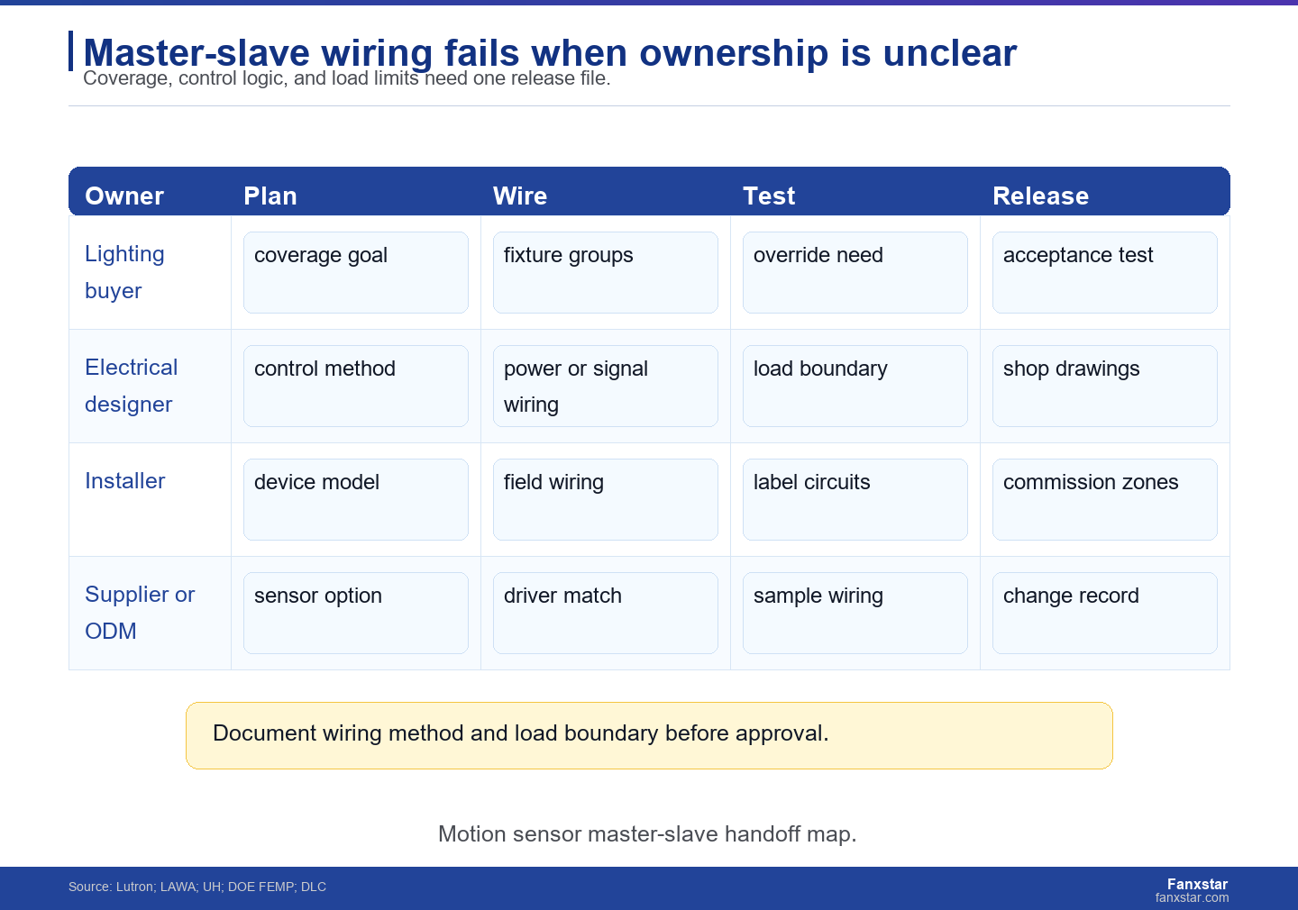
Fixture selection answers wattage, distribution, mounting, enclosure, lens, driver, and service life. Control architecture answers sensing technology, coverage, grouping, switching method, override, time delay, daylight logic, and commissioning. The two files must meet. If the fixture supplier is not told how the sensors will control the load, the driver and wiring options may be wrong.
DLC solid-state lighting technical requirements and DOE FEMP LED luminaire purchasing guidance are useful because they keep buyers focused on product category and luminaire-level performance. Sensor logic should not erase the fixture evidence. A sensor-ready fixture still needs the right optical distribution, efficiency, thermal design, enclosure, and installation suitability.
Define the acceptance test before production
A practical acceptance test names every sensor point, the intended lighting group, the switching or dimming response, delay time, override behavior, and the failure condition. For example, if a person enters from either end of a corridor, the same lighting group should respond without delay that feels unsafe. If one sensor fails, the maintenance team should know whether the load remains controllable.
For B2B buyers, this test should be agreed before production. Otherwise, the supplier may ship a sensor-ready fixture, the installer may wire a different control architecture, and the end user may blame the luminaire for a controls mismatch. The test record should include trigger distance, delay setting, override behavior, daylight condition if used, dimming response if used, and the expected failure state. Those details make the commissioning issue visible before the project turns into a warranty argument. They also help the site team separate a fixture defect from a sensor-positioning or programming issue.
Fanxstar RFQ Language for Master-Slave Sensor Projects
Send the wiring concept with the fixture request
Use Fanxstar custom LED lighting ODM service when the sensor, driver, wiring, or fixture housing must be adapted. The RFQ should state the site type, fixture model, voltage, sensor technology, whether the system is low-voltage or line-voltage, load count, master-slave or companion-device concept, override need, commissioning access, and sample test requirements.
If the buyer is not ready to specify the exact wiring, the RFQ should say so. Fanxstar can still recommend a sensor-ready product path, but the final control architecture should be validated by the electrical designer and installer before volume release. That distinction protects both the supplier and the buyer. It also prevents a fixture sample from being treated as approval for every possible sensor layout, which is a common source of field disputes.
Treat live wiring as a professional boundary
Live wiring belongs to qualified electricians working under local code, product instructions, and the project electrical design. The buyer’s role is to make the procurement boundary explicit: line-voltage devices, low-voltage sensors, multi-location circuits, emergency lighting, and wet-location fixtures should not be treated as interchangeable control accessories. If a supplier cannot name the allowed wiring method, load boundary, and device family, the sample is not ready for release.
The final buying rule is clear: approve a master-slave sensor project only when the device model, wiring method, load boundary, commissioning procedure, and acceptance test are documented. If those 5 items are missing, the project is still a concept, not a release-ready lighting system. A release file should include the fixture option code, driver type, sensor model, wiring diagram, load count, override requirement, and the person responsible for field commissioning. For repeat orders, keep that file with the purchase order so a future fixture revision does not inherit a control assumption it was never tested against.
FAQ
What is master-slave wiring for motion sensors?
It is a control arrangement where one lighting group can respond to occupancy detected from more than one sensor point. The exact wiring can vary by manufacturer, device family, voltage, relay or power-pack use, and whether companion devices are required.
Can two motion sensor switches control the same LED lights?
Sometimes, but not by assumption. Some manufacturer systems allow one occupancy sensor with companion switches, while other low-voltage systems use multiple sensors feeding a relay or input module. Always check the exact product instructions and use a qualified electrician.
What should a buyer request before ordering sensor-ready fixtures?
Request the fixture model, driver type, sensor model, wiring diagram, load count, voltage, control method, override requirement, commissioning method, and acceptance test. The supplier should confirm that the fixture and controls package match the intended wiring architecture.
Why does master-slave wiring matter for Fanxstar projects?
Fanxstar sensor-ready weatherproof, linear, and custom LED fixtures may need specific drivers, sensor openings, sealing details, and control assumptions. Defining the master-slave architecture before sampling helps prevent flicker, dead zones, nuisance switching, and installation rework.