0-10V dimming succeeds when the LED driver, controller, control wiring, zone logic, and commissioning curve agree. It fails when buyers treat the extra two control wires as proof that the installed lighting will dim smoothly.
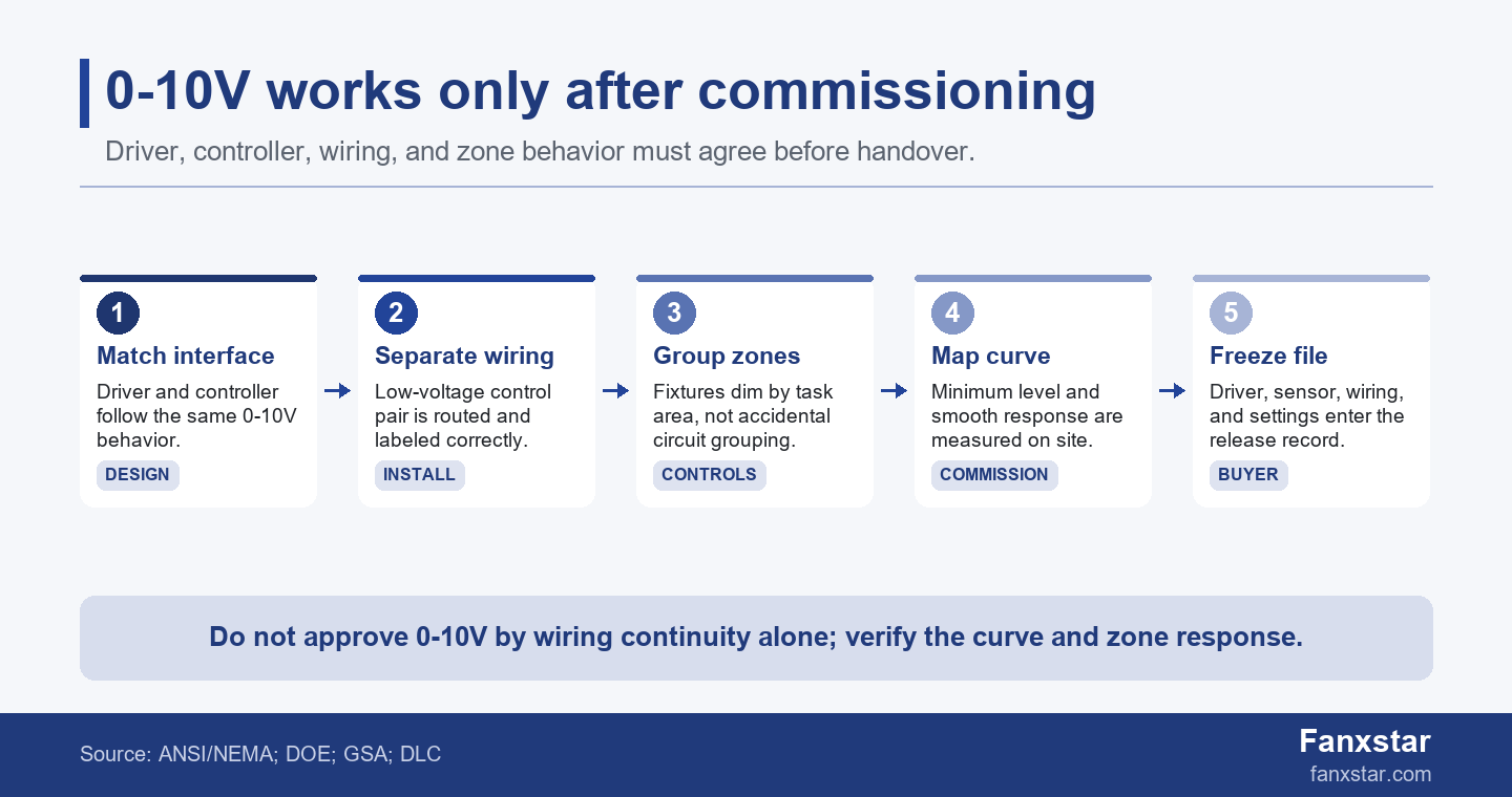
The interface is real and standardized enough to specify. According to ANSI C137.1, the standard covers the 0-10V dimming interface for LED drivers, fluorescent ballasts, and controls. According to Lutron technical guidance on 0-10V, 0-10V uses a voltage between 0 and 10 volts DC, and compatibility still matters because not every 0-10V behavior is interchangeable.
Key Takeaways
- 0-10V is an analog low-voltage control interface; it does not automatically define the whole lighting-control system.
- The buyer must verify driver compatibility, control-pair wiring, minimum output, zoning, sensor behavior, and commissioning records before handover.
- Energy savings and user comfort depend on the installed dimming curve, not only on whether a driver claims 0-10V support.
- For Fanxstar custom LED lighting, 0-10V should be specified together with driver model, sensor option, wiring route, control zone, and replacement rule.
How 0-10V dimming works in an LED lighting project
The control signal is only one layer of the system
In a typical 0-10V LED lighting setup, the driver supplies or responds to a low-voltage control signal and adjusts light output according to the control input. The line-voltage power circuit still powers the fixture. The control pair does not carry the main lighting load; it tells the dimmable driver what output level to produce.
That separation is useful because it lets a control system dim many fixtures without switching the power feed every time. It also creates a common installation risk. A fixture can be powered correctly and still dim badly if the control pair is missing, reversed where polarity matters, shared across the wrong group, mixed with incompatible controls, or left uncommissioned.
GSA LED and controls guidance notes that 0-10V dimming can require additional wiring in retrofit contexts. For a buyer, that one phrase should trigger a site question: does the project budget include the control pair, conduit or cable path, zone labelling, and commissioning time?
According to Lutron technical guidance on 0-10V, 0-10V is an analog protocol using a voltage between 0 and 10 volts DC. This is why the buyer should treat the 2 low-voltage conductors as a signal path with compatibility rules, not as a decorative accessory added after the fixture is selected.
Benefits appear only after the zone is useful
The practical benefits of 0-10V dimming are task tuning, occupancy response, daylight response, lower operating load, visual comfort, and flexibility when an area changes use. Those benefits do not come from the protocol name. They come from putting the right fixtures into the right zones and setting useful levels for actual work.
A warehouse aisle, parking garage row, data center corridor, supermarket backroom, and food-processing washdown area can all use dimming differently. One area may need occupied and unoccupied levels. Another may need manual override. Another may need a fixed high minimum for safety. The buyer should define the behavior before ordering the driver.
DLC networked lighting controls technical requirements describe continuous dimming as sufficient output resolution for smooth light-level changes. That is why buyers should not ask only whether a product dims. They should ask whether the installed system dims smoothly enough for the task and whether the minimum level is acceptable.
According to FEMP commercial and industrial LED luminaire purchasing guidance, buyers should evaluate commercial and industrial LED luminaires through a purchasing lens, not only through fixture wattage. According to DLC solid-state lighting technical requirements, qualified product programs also tie LED luminaires to tested performance categories. This means a dimming claim should be tied to a fixture, driver, and control configuration that can be repeated.
The key insight is that energy savings are not created by the letters 0-10V. They are created by useful operating hours at lower output. A 12-hour facility that holds 200 fixtures at full output all day gains little from dimming hardware; the same facility with 6 occupied hours, 4 standby hours, and 2 cleaning hours can justify a more careful control strategy.
Wiring and compatibility checks before installation
The driver, control, and wiring diagram must agree
| Check | What can go wrong | Buyer evidence |
|---|---|---|
| Driver interface | Driver and dimmer use different 0-10V behavior or minimum levels. | Driver datasheet, ANSI C137.1 claim, tested dimming range |
| Control pair | Low-voltage pair is omitted, shared incorrectly, or routed without labels. | Wiring diagram, conductor schedule, installation photo |
| Zone logic | Fixtures dim by circuit accident rather than task area. | Zone map, sensor list, commissioning scene list |
| Minimum output | Fixtures do not turn off, flicker, or drop unevenly at low command. | Measured minimum level, dimming curve, mockup notes |
| Handover file | Maintenance team cannot reproduce settings after driver replacement. | Driver model, controller model, settings export, replacement rule |
The most expensive 0-10V mistakes are often not visible in a product photo. A quotation may say ‘0-10V dimmable,’ but the project still needs a driver model, controller type, sink/source behavior where relevant, control-wire color or terminal naming, control-zone plan, and installation diagram. If those details are missing, the installer may solve the uncertainty on site.
The buyer should request a simple compatibility packet before release: driver datasheet, dimmer or control module datasheet, wiring diagram, maximum number of drivers per control channel where relevant, minimum dimming level, flicker or low-level behavior if documented, and any note about whether power-off requires a separate relay. That packet reduces arguments after installation.
Retrofits need a stronger evidence gate than new builds
A new build can plan the control pair and zone logic from the start. A retrofit inherits old conduit, switch legs, emergency circuits, sensor locations, ceiling access, and maintenance habits. A 0-10V retrofit can fail commercially even when every fixture is technically dimmable because the site cannot easily route control wiring to the intended zones.
GSA guidance for federal buildings links LED and control choices to retrofit options and notes additional wiring considerations. Use that as a buyer habit: before choosing 0-10V for a retrofit, map the ceiling access, circuit grouping, control locations, and zones. If the wiring cost is higher than expected, a wireless sensor strategy or fixture-level sensor may be more practical.
According to FEMP commercial and industrial LED luminaire purchasing guidance, purchasing decisions should evaluate LED luminaires by application and performance category rather than by one electrical feature. In practice, a 0-10V retrofit with 12 circuits, 5 ceiling zones, and 2 emergency boundaries should be checked as a site system before the fixture price is compared.
Fanxstar buyers comparing motion sensor LED lighting with 0-10V control should not treat the options as enemies. Fixture-level sensors can solve local occupancy behavior, while 0-10V can support group dimming and centralized control. The right choice depends on wiring access, task area, safety requirements, and maintenance capability.
Commissioning is where many 0-10V projects succeed or fail
Measure the dimming curve instead of assuming it
DOE's 0-10V LED streetlight study warns that ANSI C137.1 compliant drivers are not a sufficient substitute for calibrating controller output to the actual 0-10V dimming curve of a given luminaire. That finding is valuable beyond streetlights because it names the core problem: a compliant interface still needs project-level calibration.
An illustrative commissioning check can be simple. Command 10V, 7V, 5V, 3V, 1V, and the intended off or minimum state. Record whether the fixture output changes smoothly, whether the group tracks evenly, whether flicker or dropout appears, whether sensors return the correct level, and whether the control settings survive power cycling. This takes time, but it is cheaper than a full rewire after occupancy.
According to ANSI C137.1, the standard concerns the 0-10V dimming interface for LED drivers, fluorescent ballasts, and controls. The decision rule is to verify the interface first and then verify the actual fixture curve, because 1 compliant driver claim does not prove 6 useful light levels in the installed zone.
The buyer should also define what acceptable means. For a storage aisle, a rough low-level standby may be acceptable. For a retail or medical-adjacent area, visible stepping or uneven low-end behavior may be unacceptable. For emergency or egress-related circuits, dimming behavior must not conflict with local code or emergency-lighting requirements.
A small mismatch can scale across hundreds of fixtures
Based on our analysis, an illustrative 300-fixture project with 20 zones can lose more time in commissioning than buyers expect. If each zone needs 15 minutes of commissioning after wiring, the control handover alone can require about 5 hours. If mismatched driver behavior forces troubleshooting on 10 zones at 30 minutes each, the project adds another 5 hours before the facility even opens. The hidden cost is not just labor; it is schedule confidence.
That scenario explains why the buyer should freeze the driver and control file before mass production. A supplier substitution from one driver to another may keep wattage and CCT identical but change dimming minimum, curve response, or control current. If the project depends on 0-10V behavior, driver substitution should require written approval and a sample curve check.
For Fanxstar ODM projects, specify 0-10V together with the fixture platform, driver brand or approved equivalent, sensor option, control-zone behavior, and handover evidence. Relevant starting points include LED linear lighting platform, motion sensor LED lighting, and custom LED lighting design options.
A practical rule is to approve one small zone before approving the whole order. Test 6 fixtures, 1 controller, 1 sensor strategy, and 3 dimming levels before production. If the 6-fixture mockup cannot hold stable behavior for 24 hours, a 300-fixture project will not become easier after the shipment arrives.
Buyer checklist before approving 0-10V LED lighting
Turn the RFQ into a controls file
A useful RFQ should state whether the buyer needs dim-to-off or dim-to-minimum, the required minimum level, the control protocol, sensor behavior, manual override, zoning, emergency-circuit boundary, and commissioning deliverable. Without those details, the supplier may quote a dimmable fixture while the installer expects a complete controls solution.
Use Fanxstar custom LED lighting ODM service when the control behavior is part of the product design rather than a site accessory. Send the ceiling height, application, zone map, preferred driver, dimming level, sensor requirement, wiring limit, and target market. The useful deliverable is a fixture-and-driver recommendation plus a sample test plan.
Before shipment, collect the driver model, wiring diagram, label photo, terminal marking, sensor model, control channel plan, sample dimming video or measured curve, and replacement rule. The replacement rule matters because a maintenance team may change a driver years later and accidentally break the dimming behavior that the project depended on.
According to DLC networked lighting controls technical requirements, continuous dimming depends on enough output resolution for smooth perceived changes. A practical RFQ can translate that into 4 acceptance points: minimum output, maximum output, 1 mid-level setting, and 1 standby or off behavior tested on the actual driver-control combination.
Use 0-10V where it has a real operating job
0-10V is not always the best answer. It is a strong fit when the project needs predictable dimming zones, integration with controls, standby levels, daylight response, or manual scene adjustment. It is weaker when the site cannot run control wiring, the zones are small and scattered, or the maintenance team has no way to preserve settings after replacement.
The final decision should compare three things: wiring feasibility, control value, and commissioning effort. If all three are favorable, 0-10V can be a reliable and familiar choice. If one is weak, a sensor-integrated fixture, wireless control, DALI, or simpler switching strategy may be safer. The best lighting-control decision is the one the building can install, operate, and maintain.
FAQ
Does 0-10V dimming need extra wires?
Yes. A 0-10V LED lighting project normally needs a separate low-voltage control pair in addition to the power conductors. The buyer should confirm the wiring route, control terminal labels, zone grouping, and installation responsibilities before approving fixtures.
Can 0-10V dimming turn LED lights completely off?
Sometimes, but not always. Some systems dim to a minimum level and need a separate relay or switching method for full off. Buyers should ask whether the specified driver and controller support dim-to-off or dim-to-minimum and should test the intended behavior.
Why do 0-10V LED fixtures flicker at low levels?
Low-level flicker can come from driver behavior, controller compatibility, wiring noise, load grouping, or a minimum level that is too low for the fixture. The buyer should test the actual driver and control combination at several command levels before approving production.
Is 0-10V better than a motion sensor?
0-10V and motion sensors solve different problems. 0-10V controls dimming level, while a motion sensor detects occupancy and triggers behavior. Many industrial projects use both, but the buyer should define zones, standby levels, override rules, and commissioning evidence before choosing the final setup.